 |
|
|
|
|
|
Welcome to the Website for N5814L The Online Refurbishment Record of 1972 Grumman AA-5 Traveler N5914L Serial Number AA5-0014 |
|
|
|
Galleries |
|
Links |
|
|
|
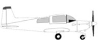
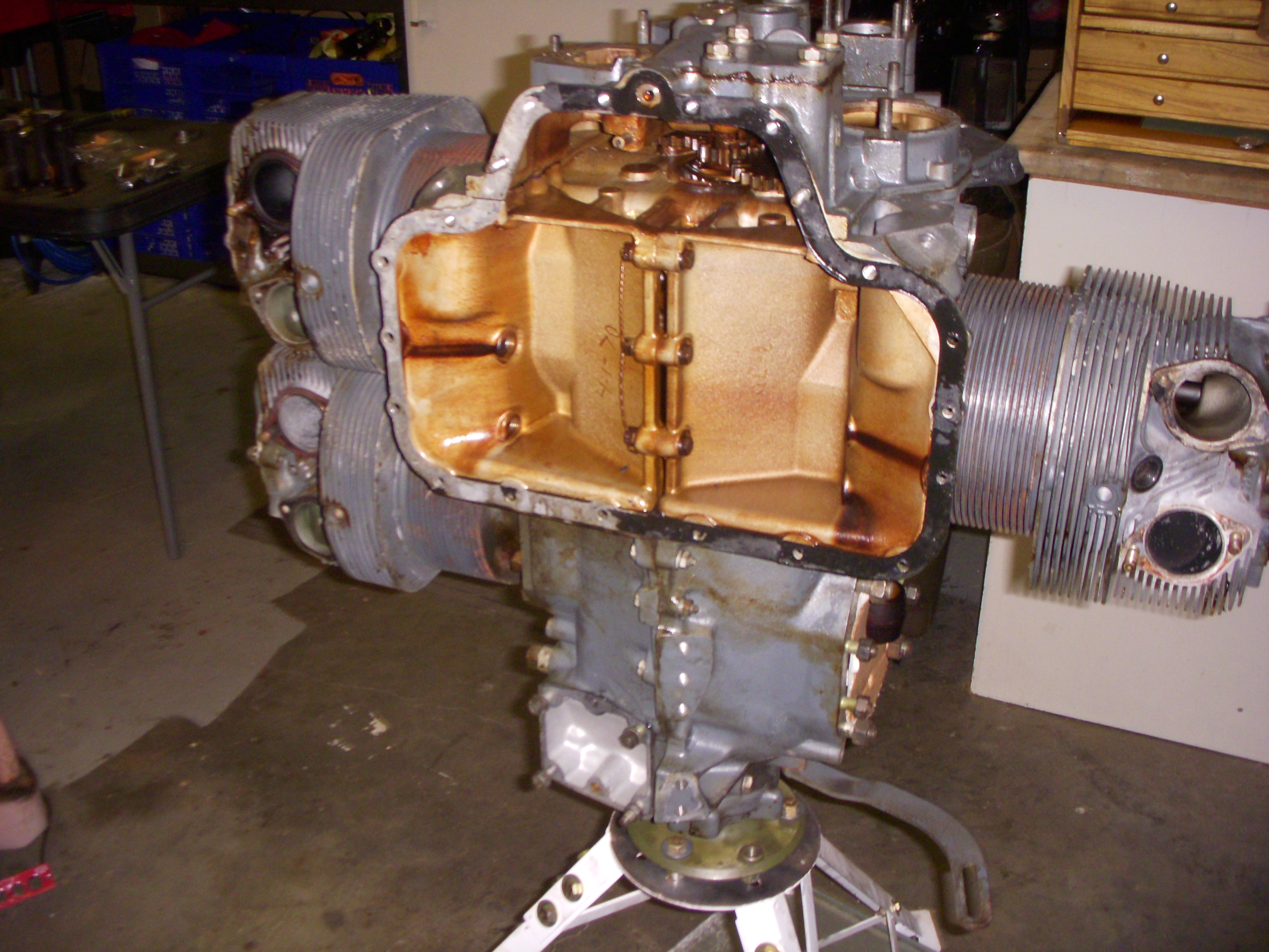
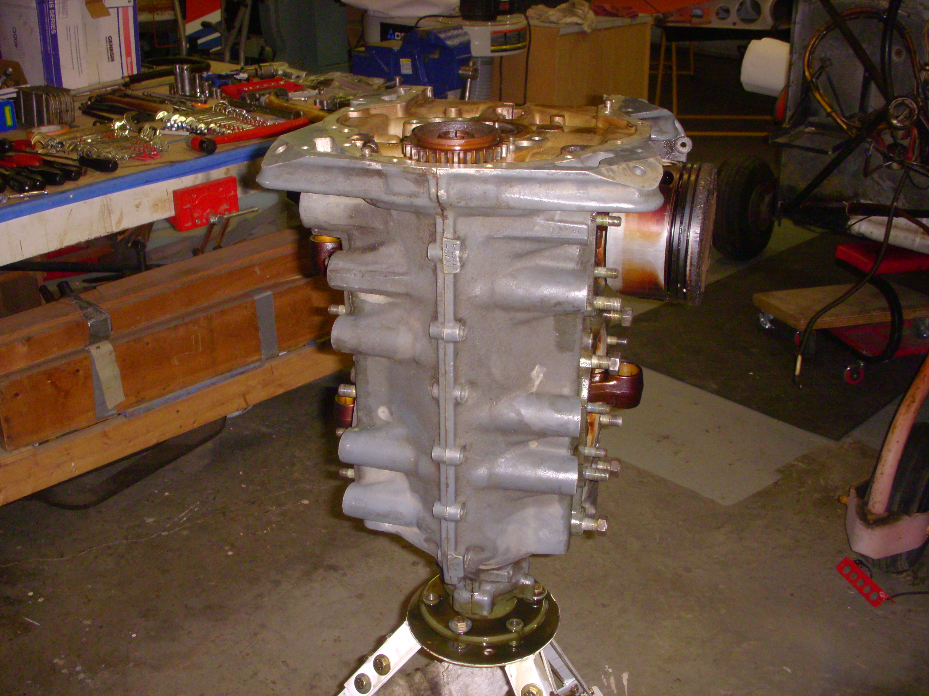
Engine and Firewall Forward Once 14L was comfortably bedded down in my shop, we figured, given the turnaround time on all the specialty repair stations, that there was no time like the present to get the ball rolling on the major overhaul. Darryl had built a lovely engine stand and I wasted no time getting the 14L's O-320-E2G bolted to it and standing up on its prop flange. |
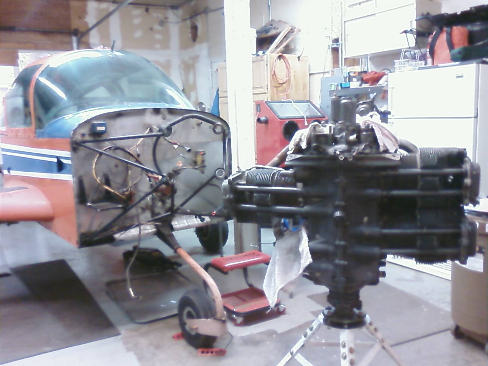 |
| Knowing the limits of my "off-line brain," I took lots of photos as I worked my way through engine removal and disassembly. Engine-driven fuel pump, left side. |
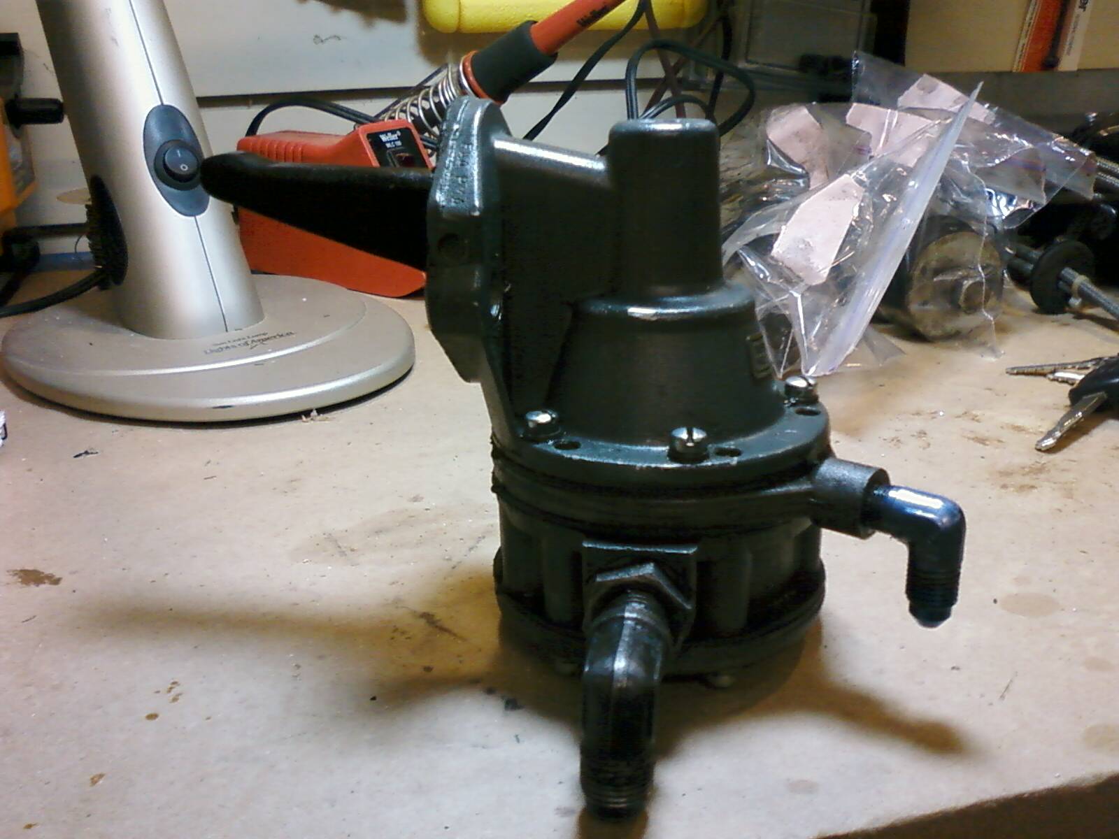 |
| Engine-driven fuel pump, right side. |
 |
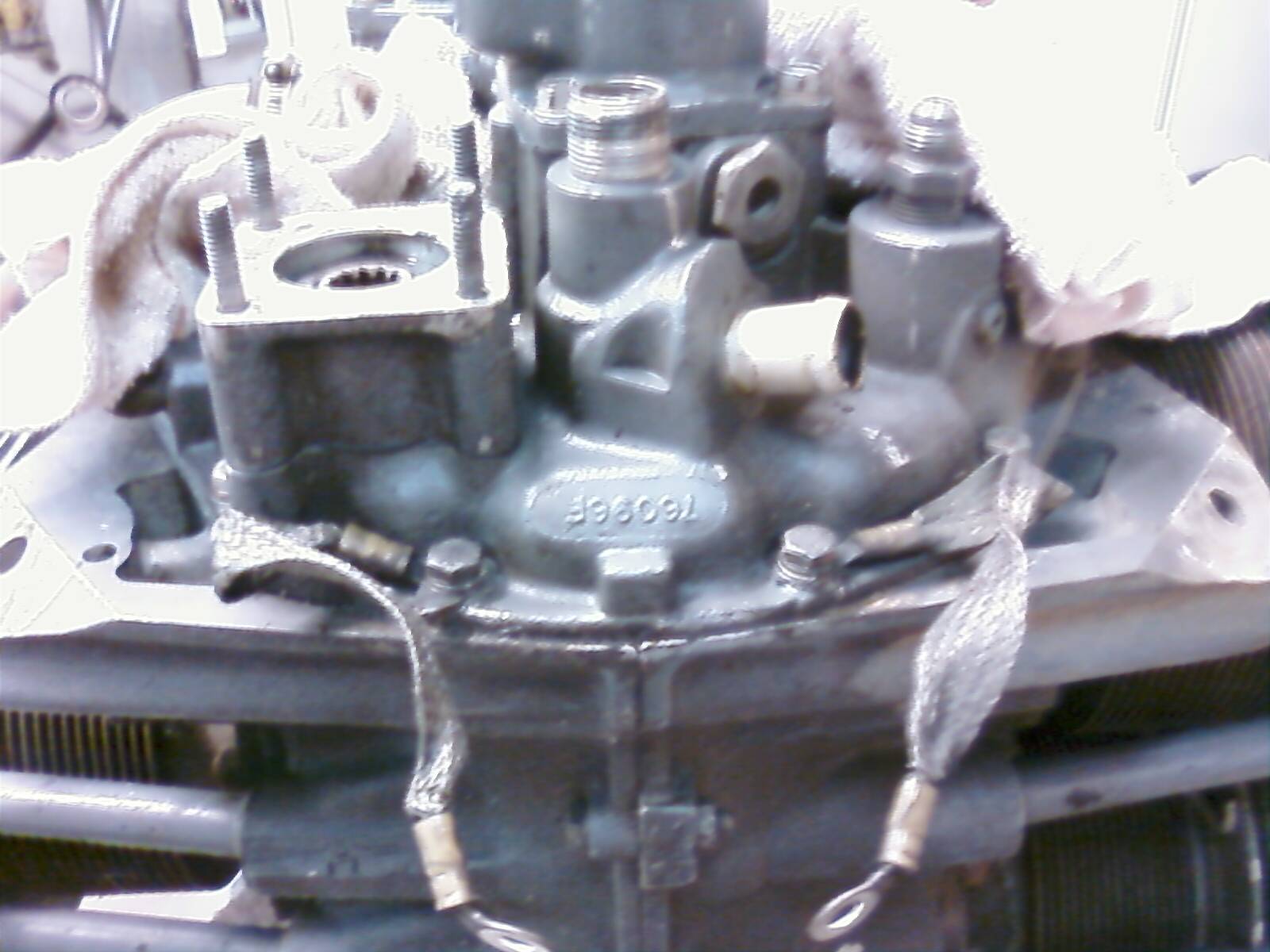
| More memory aids. This is "cell phone photo" of the top of the accessory case detailing the location and orientation of the engine bonding straps. |
 |
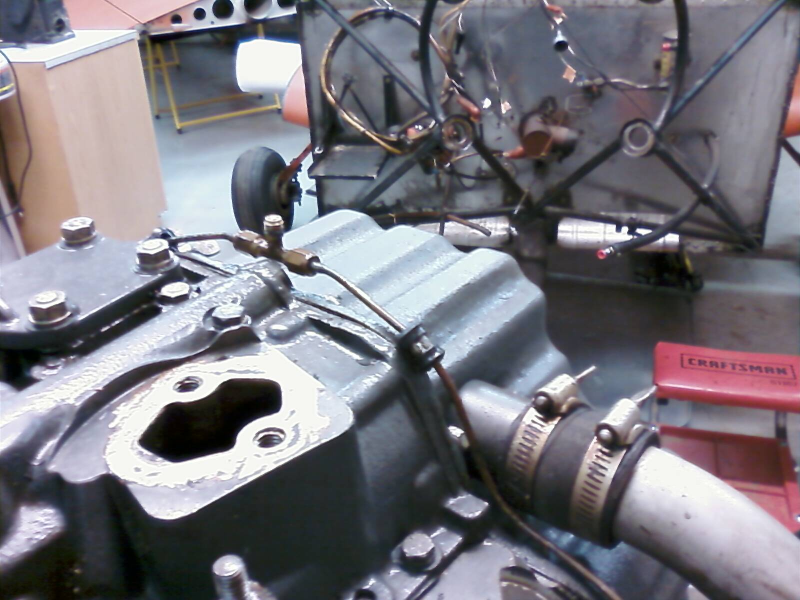
| A shot of the primer line Tee-fitting from across the accessory case, showing the orientation of the fitting and the locations of the primer line Adel clamps. |
 |
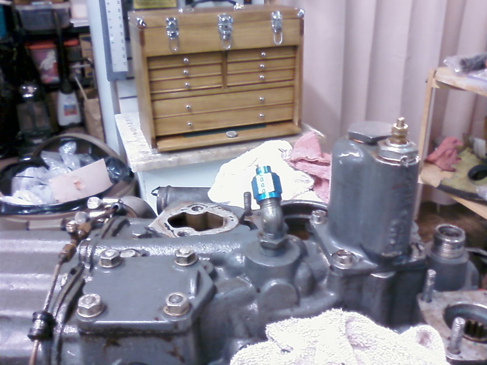
| A shot of the accessory case showing the orientation of the oil cooler hose flare elbow. |
 |
| The denuded accessory case. |
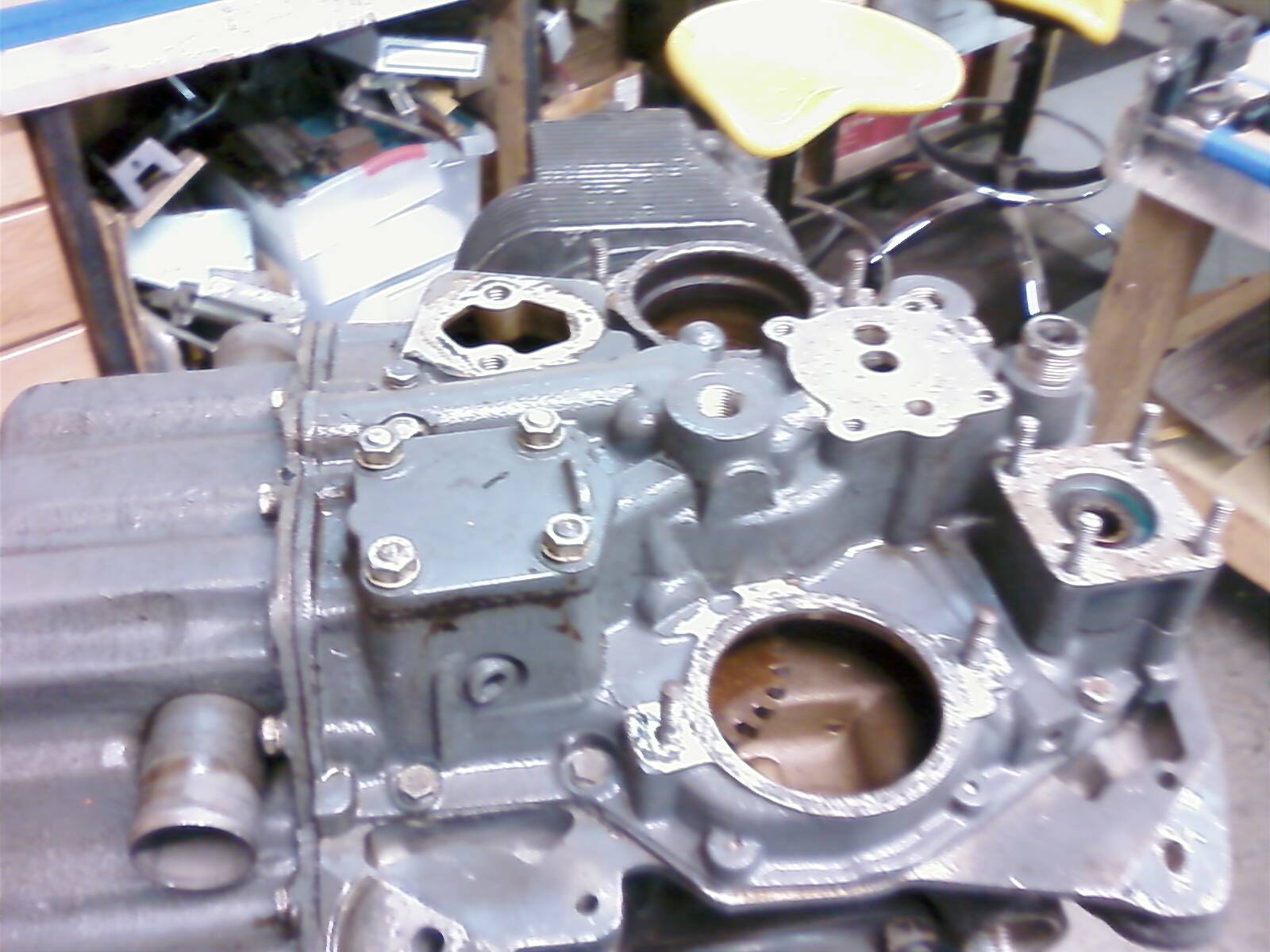 |
| Oil pan off. Accessory case and all backbone bolts are next. |
 |
|
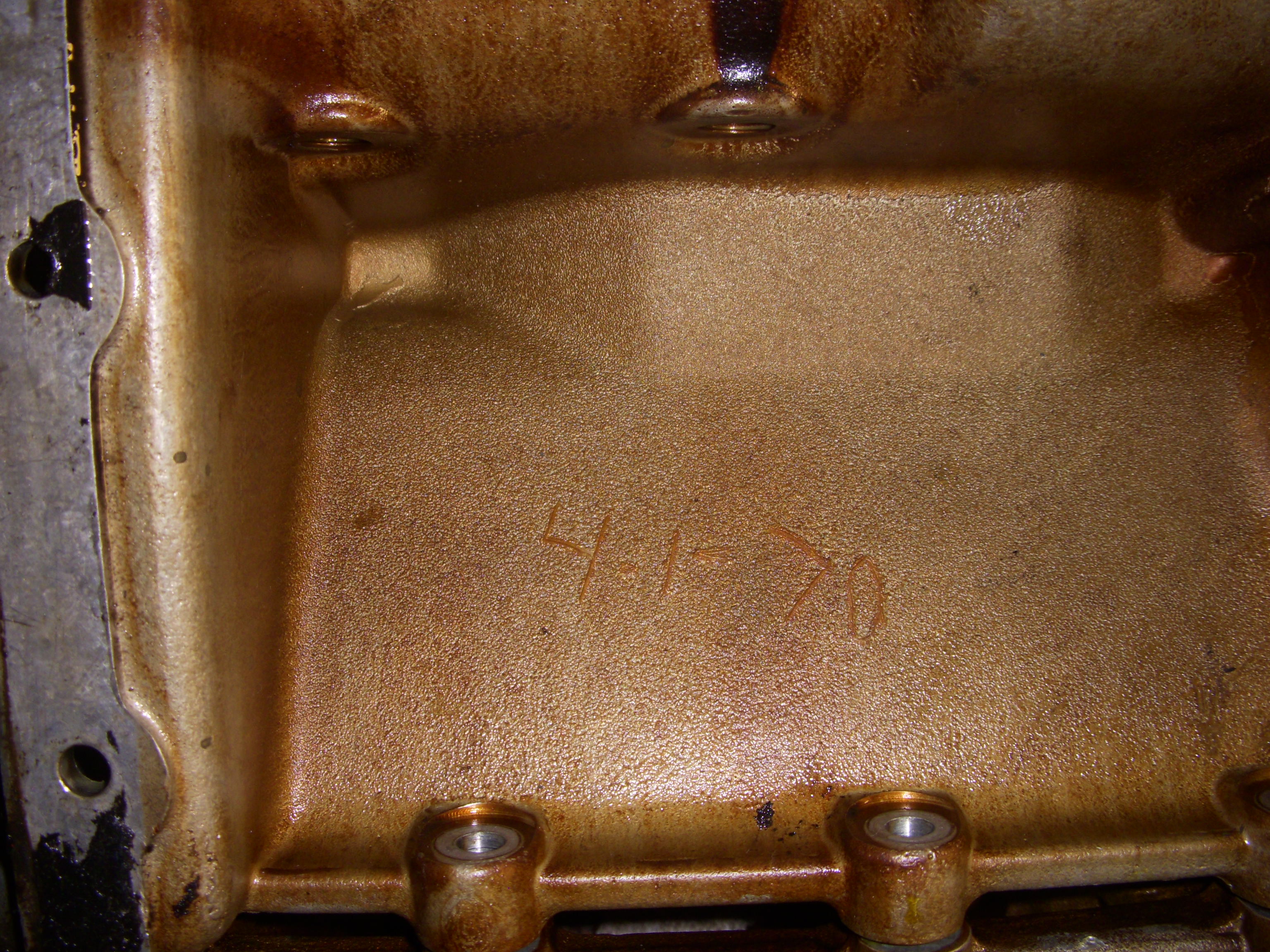
What's this?! Our O-320 is an April Fool's Day engine! After
removing the oil pan, the date 4-1-70 could be clearly seen scratched into
the lower case casting. How fitting that this Web page was inaugurated
on its 39th birthday. There's no way I'm going to exchange this case
now. I have to get it back OHC. At least April Fool's Day 1970 was a Wednesday! |
 |
| The accessory case, gears, shafts, and oil pump are gone, and all the backbone bolts are out |
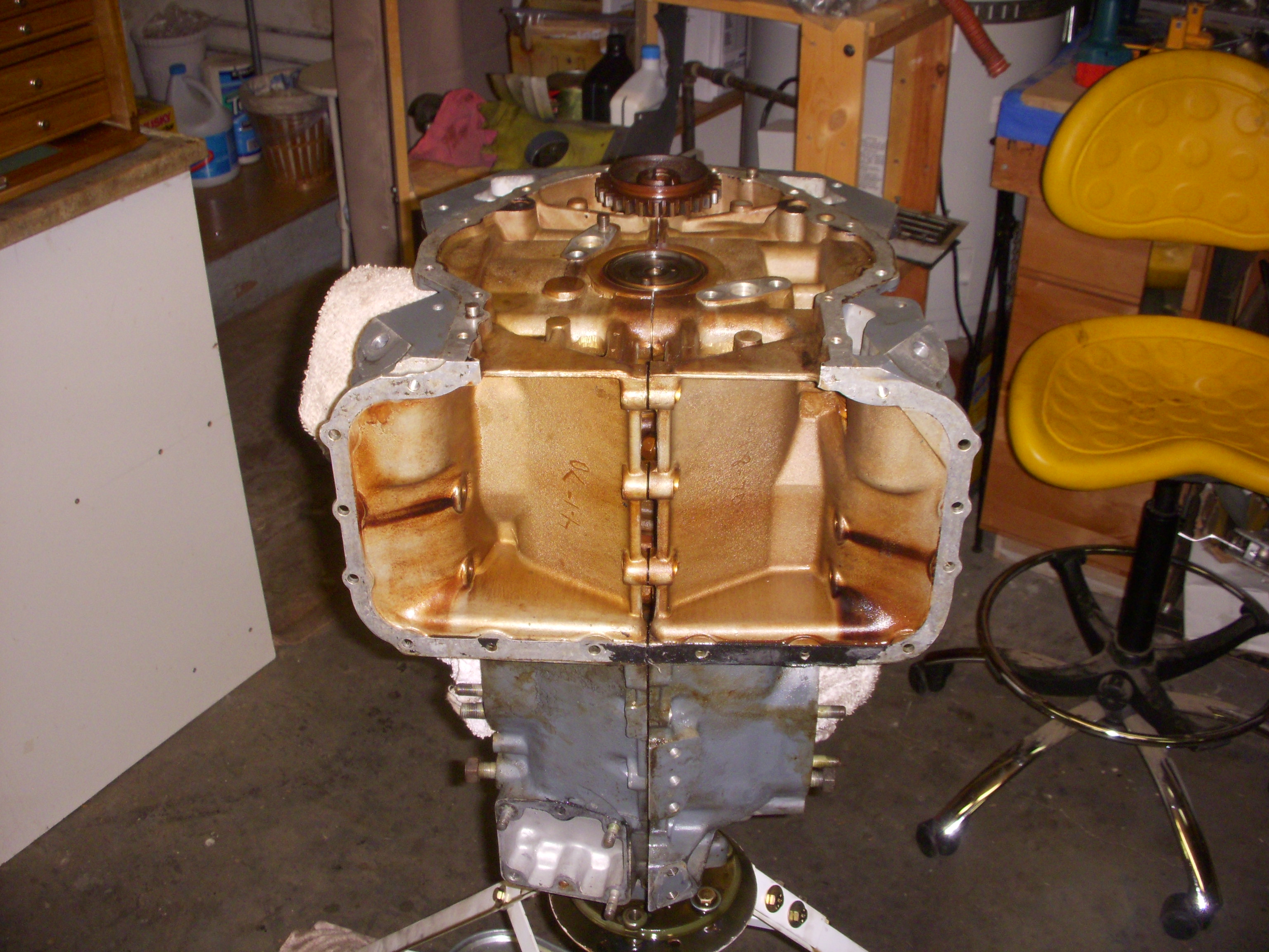 |
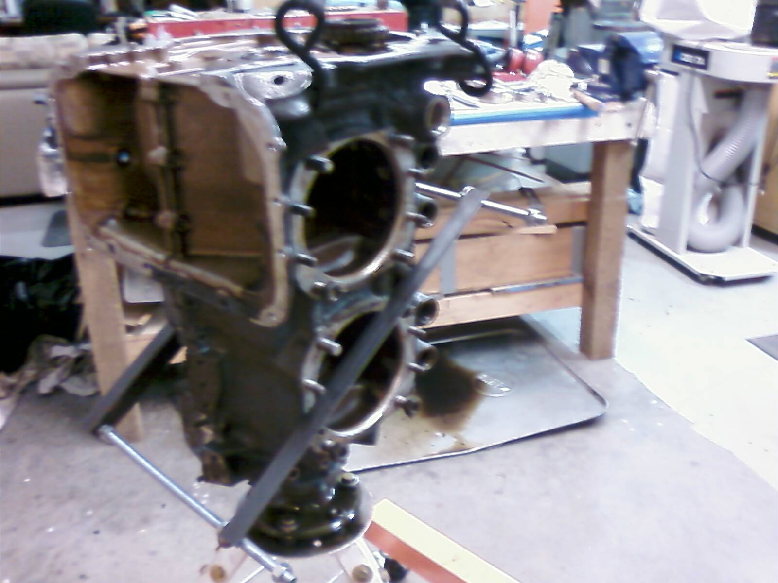
| The case is almost ready to split. |
 |
|
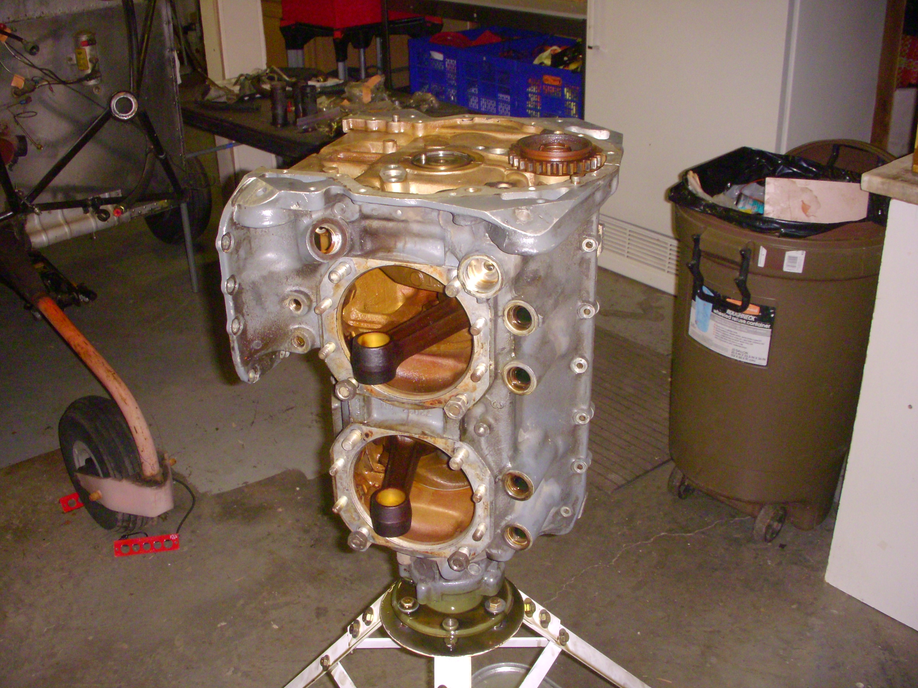
One pesky piston hanging on. All of the piston pins were completely dry, varnished, and very tight, but this one was ridiculous. Rather than trying to beat it out with a mallet and phenolic drift while it was on the on the engine, I chose to disassemble and remove all of the connecting rods before splitting the case by working through the cylinder skirt openings. The errant piston pin was finally driven out on the bench with stunning difficulty. |
 |
|
I'm by no means an engine guy, but I've split a few Lycomings. This case put up more of a fight than any I've tackled. I finally went out and bought some angle iron and all thread in an attempt to approximate the function of the special "pressure plate" tool shown in figure 7-16 of the Lycoming Direct Drive Overhaul Manual. |
 |
| It got things moving, but there was still a lot of cajoling to do before the case halves finally separated smoothly. I pretty quickly came to wish that I'd just left them together... |
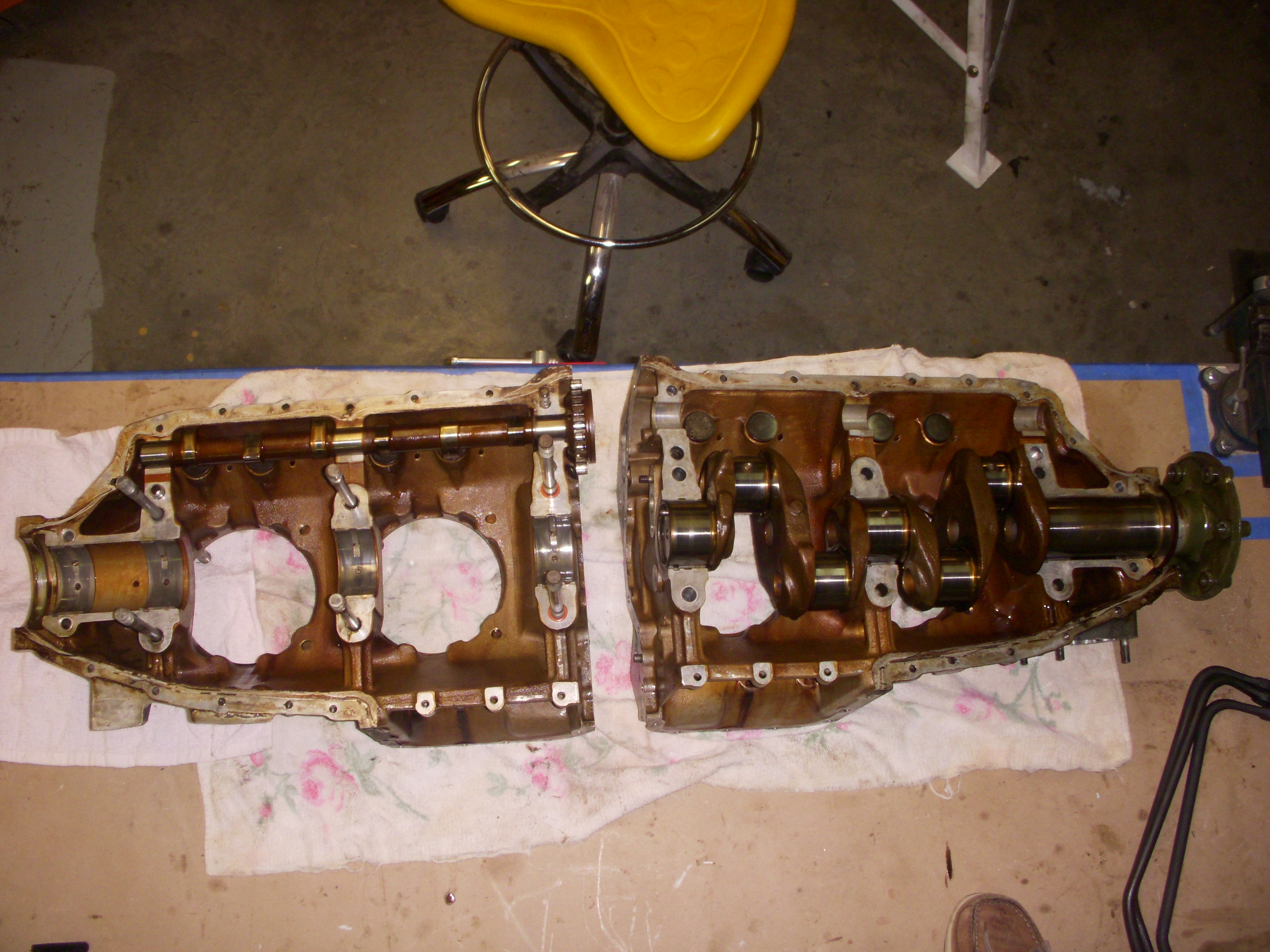 |
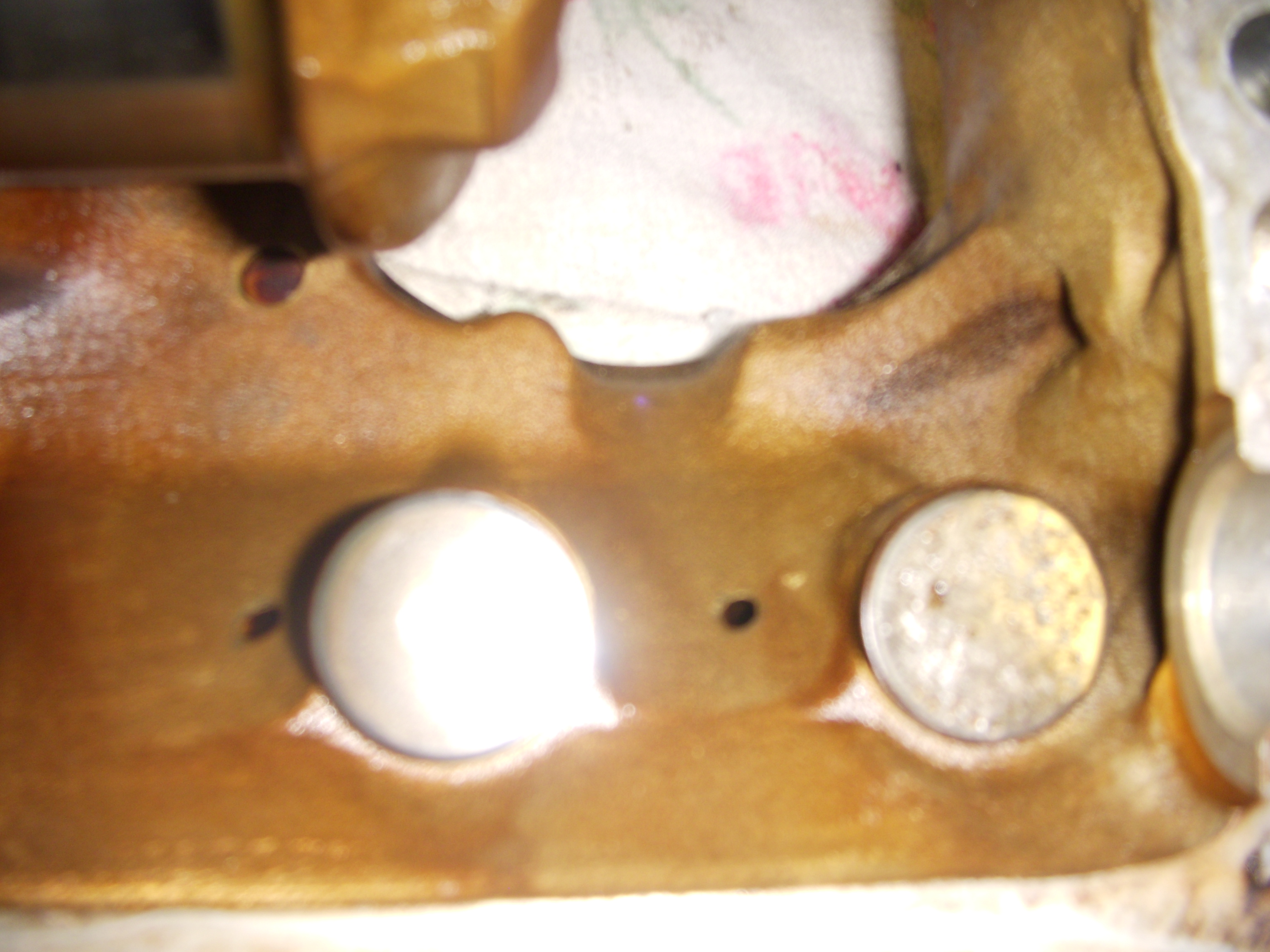
| During the prepurchase inspection, we had pulled the #1 cylinder and got a pretty good look at most of the lifter body faces. The only ones we couldn't see at all either directly or with a mirror were the #3and back #4 lifters. They say its the one you don't see that gets you. Here's a close up of the the brutally spalled #4 lifter face. |
 |
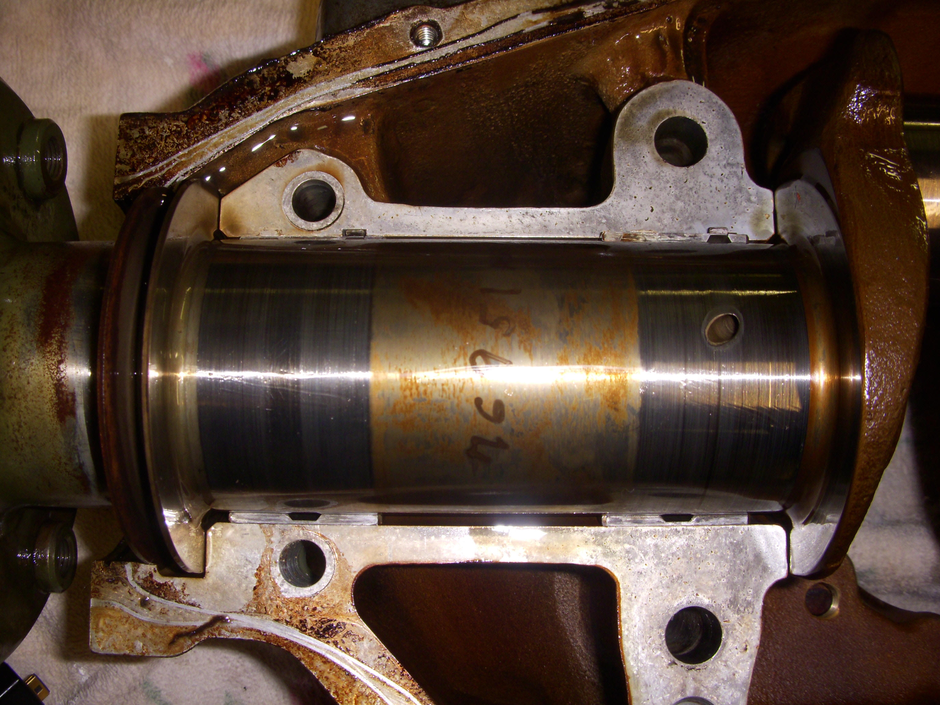
| Now the main journals are revealed, The front journal, in particular is pretty "rippled." It will be interesting to see what Aircraft Specialties has to say about it after they've had a chance to look it over. |
 |
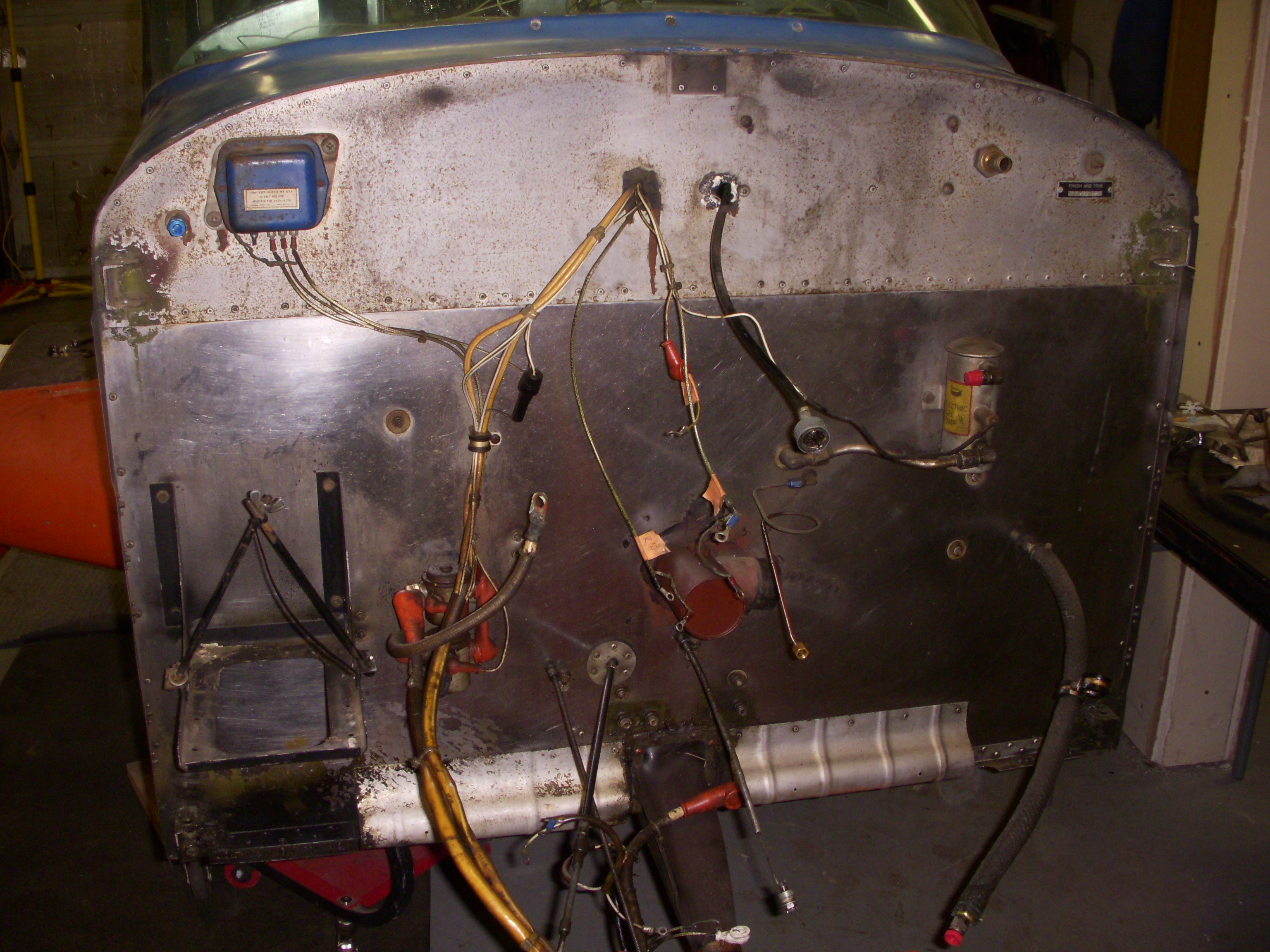
| Darryl has removed the engine mount for stripping, corrosion control, and repainting. Now the firewall is nicely laid bare for a through inspection, scotch-brighting, and repair as needed. Not the opening around the tack cable where I removed a mass of bathtub caulk. That was also the point thought which the deteriorated EGT/CHT leads had been fed. |
 |
This page last updated on 08/06/2018