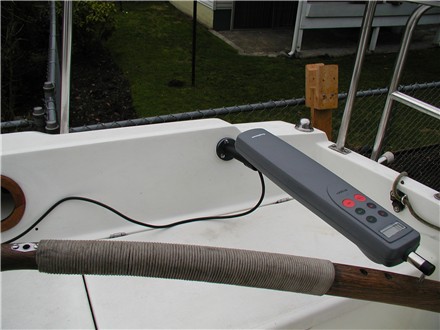
Raymarine ST1000+ Tillerpilot Installation
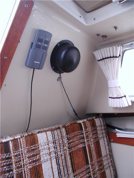
Hmmm... wonder if I need to worry about any impact on compass deviation - that's it right next door.
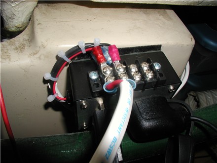
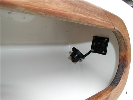
To economize on the number of conductors used in the harness, signal-grounds were run on the negative power lead. Also, since there are positive connections here, the terminal strip will be covered.
Note that the GPS portion of the installation currently uses a serial/power cable with separate connectors for data and power. The GPS is powered through the cigarette-style outlet. This will eventually be replaced by a custom-build serial-style cable connector through which the GPS will also be powered. When this is one, an inline fuse will be added to the box for GPS power.
Clearly, it's time do some scrubbing in here.
As long as we're here with the camera...
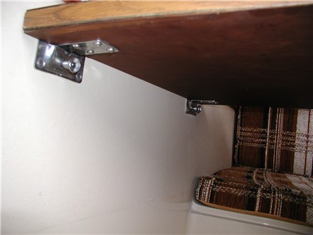
Note, however, that any force placed on the table edge is now transmitted to and borne by the table mounting screws and cabin liner. They were not intended for this shear load, so I still try to avoid leaning on the table.
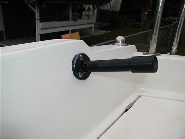
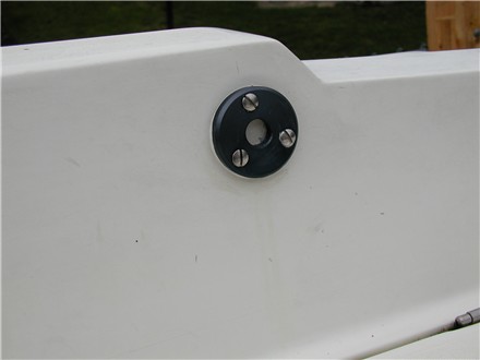
Installation note: I drilled the holes slightly undersize and then opened them up with a tapered repairman's ream for something just on the loose side of a "light-dive" fit. That is, the pins take a little effort and jiggling to line up and insert, but there is zero play when they are in place. Hopefully, this will prevent fretting between the pins and the brackets.